How are your measurements adding up? Do you need automation combined with a high level of accuracy? Or perhaps, your application demands a portable measurement device for its ability to reach difficult to measure features? With the ever growing need for accurate measurements in a rapid paced manufacturing industry, knowing the best type of universal 3D dimensional measurement device available for your application will help streamline both your manufacturing and quality inspection processes.
What is a CMM?
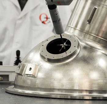
Coordinate Measuring Machines (CMMs) are mechanical systems that use measuring transducer technology to convert probe and physical measurements of an object's surface into electrical signals that are then analyzed by specialized metrology software. There are many different types of CMMs;  the most basic systems use hard probes and XYZ read-outs, while the most complex employ fully automated continuous contact probing. For a system like a bridge CMM which uses this set of axes, each axis is used to indicate the system's position or location in space. The probe head determines the values on the Z-axis by moving up and down the system's bridge. The system's Y-axis determines its values by moving over the entire CMM's base. The values for the X-axis are determined by moving back and forth across the bridge.
Stationary CMMs such as bridge type CMMs, provide quality assurance with efficiency, accuracy, and flexibility due to their programmability. They can be set up for automated, repeated measuring tasks which do not need to be reprogrammed each time. In general, CMMs come with a wide array of sensors and probes and are ten times more accurate than articulating arms. However, due to the sensitive nature of these measuring instruments such as contact and vision-based probes as well as vision and laser sensors, which comprise most CMMs, a temperature and humidity controlled environment is an important factor to consider prior to incorporating a system into the quality inspection process. Unlike articulating arms which offer portability, CMMs are usually stationary or cumbersome to move. Also, there are a number of different software programs that run the machines, which would mean a significant investment in training CMM operators.
What is an Articulating Arm?
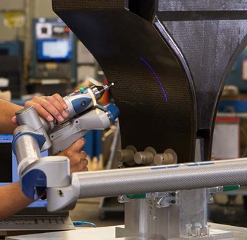
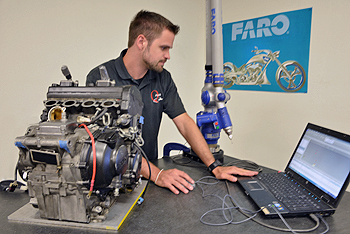
An articulating arm is a type of CMM that uses rotary encoders on multiple rotation axes instead of linear scales to determine the position of the probe. These manual systems are not automated, but they are portable and can reach around or into objects in a way that cannot be accomplished with a conventional CMM to perform 3D inspections, tool certifications, CAD comparison, dimensional analysis, reverse engineering, and more. The movement of the articulating arm allows for ease of use, as well as a broader scope of measuring ability as it pivots at the wrist, elbow, shoulder, and base of the system. The encoders at the system's base triangulate the location of each joint to the probe tip in 3D space.

The measurements of very large parts can be easily accommodated by moving the articulating arm into another location around that part. The system's robust software is able to compile the measurement data from these individual locations and stitch all the data together to extend the measurement volume.
The ability to easily transport a highly accurate system such as an articulating arm allows users to take measurements onsite and in difficult to reach scenarios, without having to disassemble parts or transport large and heavy parts onto a fixed base. Improvements to articulating arms also include the integration of laser line scanners in combination with the traditional touch probe, thereby allowing the system to seamlessly scan across a diversity of surface materials, including those with high contrast, reflectivity, and geometric complexities. Unlike fixed CMMs, the probe of an articulating arm is not restricted to travel within the extent of a confined measurement bed. However, compared to the CMM which can be programmed to automate measurement, the articulating arm is manual and dependent on the operator to take measurements by moving the probe to each location on the part, and produces measurements which are generally less accurate than the fixed CMM. Operators will also have to learn to adjust to the motion of using the articulating arm, as it is fixed to a base.
Consider All Factors
There is not a single particular factor that will determine if a CMM or an articulating arm is best suited for your specific application. However, factors to consider that will inevitably affect the final decision will include:
- Accuracy of measurement results
- Portability of the system
- Size of the parts being measured
- Features that will be measured
- Degree of automation required during measurement
- Cost of the system
- Cost of training operators
Q-PLUS Labs has been a leading dimensional measurement laboratory since 1987 and, in addition to its wide array of services and products, specializes in helping companies find the right measurement solutions to meet their needs. Contact us for answers to your dimensional measurement and inspection questions or to request a quote.


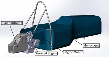
 Fullerton's SAE uses a Yamaha R6 Motorcycle engine, a large displacement choice for the 610cc class. The car's design utilizes the R6 engine as a stressed member to connect the drivetrain to the cockpit. This type of engine design requires the chassis to work with the engine as an active structural element of the chassis to transmit forces and torques, rather than using standard anti-vibration mounts to passively contain it. The R6 engine was chosen based off its high power output and ability to be used as a stressed member. In conjunction with suspension design and tire selection, the engine weight works well to keel the tires while heated under the track's conditions.

