Q-Plus Labs

Sitemap | Contact Us 

Dimensional Measurement Blog

3 Surprising Facts about Dimensional Inspection

Posted by Mike Knicker on Nov 30, 2016 2:22:19 PM

 3 Surprising Facts About Dimensional Inspection.jpg

When you think about your daily life the topic of dimensional inspection will likely never come up. In fact, many people could go through their lives not understanding how dimensional inspection works, let alone how it fits into almost every aspect of their daily lives through the products they use. From the coffee cup that you may be holding right now as you read this article to the car you drive (hopefully not while you are reading this article), dimensional inspection was an integral part of the manufacturing process for all of the products you use in your daily life.

What Is Dimensional Inspection?

Simply put, dimensional inspection is the measurement of the distances between different features on a part. If you have a block that is supposed to be one inch long, then dimensional inspection will tell you exactly how long that block actually is. This is a simple case, but think about the intricate measurements required to make sure that each individual part of your car engine will fit together properly in order to move the pistons for you to be able to drive your car.

Even your simple water bottle needs to have very close dimensional measurements in order for the bottle top to screw onto the bottle and provide a tight seal for the water; if the dimensions are not correct then you may have trouble storing the bottle without spilling its contents, or even have an issue trying to fit the lid back onto it once you’ve removed it. This ability of the parts to connect correctly is designed into the dimensions of each part, but dimensional inspection of the individual parts to make sure they meet the design is what ensures the end product will work when it gets to you.

When it is not feasible to measure each dimension on each part, (for instance water bottles would become very expensive), dimensional inspection is used on the tools that make the parts such as injection molding dies that form a water bottle out of molten plastic. If the tool dies are ensured to have the right measurements, then the resulting bottles will be correct; a company can then check a sample product at intervals to make sure that the forming process is working properly as it progresses. So even then dimensional inspection is used on a sample basis.

Dimensional Inspection: 3 Surprising Facts

It should no longer surprise you that dimensional inspection is found throughout the manufacturing processes of almost every product that you use to ensure the safety and integrity of those products, but there are still some facts about dimensional inspection that you might find surprising.

  1. Tight tolerances: Dimensions are never measured to exactly what the design measurement should be (called the nominal dimension) so each design will have a tolerance on the dimension; basically, a stated amount that the dimension can be different from the nominal dimension. So, if you have a measurement that needs to be at one inch, but can be different from this measurement by one-sixteenth of an inch, your tolerance would be +/- (plus or minus) one sixteenth of an inch. In some industries, such as the space industry that builds satellites or parts for the space station these tolerances can be very tight, such as one ten thousandth of an inch (0.0001”) in order for the parts to work reliably in the space environment. This is for the safety of the astronauts or for the reliability of the satellite since you cannot fix a problem once in orbit.

  2. Tighter measurements: A general rule of dimensional inspection is that the dimensional measuring equipment should be ten times better than the tolerance being measured. That means if you are measuring something to the nearest inch your measuring equipment needs to be able to measure to one tenth of an inch. For the above example, if you are measuring to one ten thousandth of an inch (0.0001”) your measuring equipment needs to be accurate to one hundred thousandth of an inch (0.00001”). So, dimensional measurement equipment can be extremely accurate.

  3. Calibration: Equipment for dimensional inspection needs to be checked on a regular basis to make sure that it is still measuring as accurately as it is designed to measure. This verification is done against a very accurate standard part or specimen that has been designed and verified to a certain dimensions and tolerances. By ensuring that the dimensional equipment measures the standard correctly you can be confident that the equipment is functioning properly. Most of these standards are traceable back to the National Institute of Standards and Technology (NIST), which is part of the United States Department of Commerce, but is a non-regulatory agency. NIST is the foremost measurement standards laboratory and is used as the standard for calibrations in most industries.

Dimensional Measurements: In-House or Outsourced

While many companies keep all of the equipment they need to perform all of their dimensional inspections sometimes the equipment is so expensive, and the measurements taken so infrequently, that it makes more sense to have an expert laboratory do the measurements for you. In either case the experts at Q-PLUS are the place to turn for either help on the right equipment to purchase, or the accurate tools to measure your most intricate dimensions and the skilled operators to run that equipment.

Q-PLUS Labs has been a leading dimensional measurement laboratory since 1987; providing one place for precision measurement solutions. As a lab registered to ISO 9001 and accredited to ISO 17025, you can be certain that you will get the right dimensional measurements and calibrations every time.

New Call-to-action


Read More

Topics: dimensional measurement, dimensional inspection, dimensional inspection equipment, dimensional measurement services, nano, measurement services,, nanomeasurements

Nano measurements: 3 basic factors for determining the value of your measurement data

Posted by Mike Knicker on Nov 4, 2016 12:29:05 PM

 Nano measurements 3 basic factors for determining the value of your measurement data3.jpg

With the rapid development of technology comes the greater need for the increased accuracy in measurement capabilities that are able to keep up with the pace of products being manufactured at the nano level. For precise accuracy up to the micrometer, such as 3D measurement data of a needle tip or surface roughness measured to extreme accuracy, nano measurement is the logical solution for these intricate measurements. But how do you know if it is worth your time to invest in this specific measurement solution for your application?

Of course, every measurement technique has its challenges, and with the various methods of nano measurement, there are generally three things to consider when choosing the best method for your application; specifically measurement accuracy, speed, and cost. While there are two main methods of acquiring nano measurement data, optical-based and contact-based, you will need to examine these three basic criteria when you are weighing your decision on which type of method to implement.

Accuracy of measurement

What benefit will this measurement data provide your application? To measure in the nano realm, there are two types of methods. One way is via contact-based methods of nano measurement which can give very high resolution measurements with high accuracy. This is due to the fact that they come in contact with the surface of the part being measured, so that certain features the probe comes in contact with can more easily be distinguish, and thereby measured accurately. However, parts that may become compromised if they come into direct contact with the measuring device would not be suited for this particular form of measurement.

This is only a general rule of thumb, however, as white light interferometry, a type of optical-based measurement, is one of the most accurate methods possible even though it does not come in contact with the measured unit.

Speed of measurement

If you are looking for a faster measurement solution, an optical-based method of nano measurement may be the best option, because this method uses light to take the measurement and does not physically come into contact with the surface that it is measuring. This process speeds up the collection of measurement data without the risk of surface damage, unlike what can be experienced with a probe used in the contact-based methods.

One drawback of these faster methods of measurement may be the loss of some resolution on surfaces with high aspect ratios; such as a surface with features such as steps, slopes, holes or sharp edges. These can be much more accurately measured with a contact-based method, but this will be more time consuming in order to protect the surface of the piece being measured.

Cost to measure

Of course different measurement systems will have different financial costs associated with them, and this will have to be weighed when choosing the right system to meet your needs. When making your decision on accuracy, precision, and speed you will need to keep in mind how much the measurement data will cost. Along these lines, the following are some things to consider:

  1. Will it be more cost efficient to purchase the equipment to perform your measurements in-house; or would it be better to outsource this activity to a lab that specializes in these measurements? If you manufacture a part in-house and need to perform repeated measurements, then it might be in your best interest to invest in the equipment and training necessary to do the measurements yourself.

  2. A major benefit of going to a lab for your measurement needs is the specialization that they have in performing these measurements with the appropriate training, experience and equipment to give you the data you need. Labs are fairly flexible and can be great assets for measurements of one-off parts as well as large ongoing jobs.

While you can make some adjustments to reduce the cost per part, such as reducing the sample frequency of measurements, ensuring that you get exactly the type of measurements for the data you are looking for is one of the best ways to reduce your cost overall.

Having difficulty getting started on your measurement project? Since 1987, Q-PLUS Labs has provided a one stop solution for precision measurements to our customers. As a leading dimensional measurement laboratory, we have been able to not only supply measurement services and calibrations as needed but also consult on, specify, integrate, and sell in-house measurement solutions to meet the many and varying needs of the manufacturing industry. As a lab registered to ISO 9001 and accredited to ISO 17025, we've built our reputation on providing objective, unbiased information whether it be from our lab services department or our metrology products division.

New Call-to-action


Read More

Topics: dimensional measurement, dimensional inspection, dimensional inspection equipment, dimensional measurement services, nano, measurement services,, nanomeasurements

Q-PLUS Labs' Case Study: California State University, Fullerton's Formula SAE Team's Race Car Engine 3D Scanning

Posted by Mike Knicker on Sep 9, 2016 1:20:03 PM

 CSUF_SAE2016_banner.jpg

California State University, Fullerton's Formula SAE chapter is back from their brief break to build another beast of a race car. Using Q-PLUS Labs' 3D scanning expertise to aid them, the team enters into their 3rd year in the challenging Formula SAE competition which encompasses designing, building, and competing a mini-formula style race car that will be evaluated for its potential as a production item.

Introduction

1_DSC_3074.jpgThis year, California State University, Fullerton's Formula SAE is using a Yamaha FZ-07 motorcycle engine which has increased displacement for their new race car design. The new design for the chassis will include a space frame as well as a carbon fiber driver cell. The space frame is created by welding steel tubes together and attaching them to the cockpit and the engine housing, as well as the drive train. Unlike the team's last design which was a stressed engine, this design will be mounted to the inside of the space frame. Weighing 20 to 30 pounds less than the team's original engine, this choice also offers more torque and faster acceleration without creating a heavier car which would give the team an edge against their competition.

Our Process

Because the final race car's design needs to be both fast and safe and relies on the integrity of the engine's measurements, Cal State Fullerton's SAE sought the expertise of Q-PLUS Labs' dimensional measurement engineers. Using the Steinbichler Comet 5, Q-PLUS Labs was able to provide CSUF's SAE team with accurate measurements of the engine to provide the structure for the race car's design. Using these points from the scan data, the team can proceed to confidently to create a CAD model of the car designed with both the driver's safety and structural integrity in mind. Follow CSUF's Formula SAE's journey and results here in our future blog post.


New Call-to-action


Read More

Topics: 3D scanners, 3D Scanning, 3D scanning equipment, case studies, Steinbichler, Cal State Fullerton, Baja SAE

Q-PLUS Labs' Case Study: Extreme Components, LP's Surface Finish Analysis of DAT Mold Interlocks

Posted by Mike Knicker on Aug 12, 2016 12:47:02 PM

 banner_extreme-components.jpg

Extreme Components, LP is known for designing and creating cost-saving, effective alignment/positioning devices for the Injection Mold Industry that are durable, reliable, and high precision. Their molding alignment locks are manufactured using dynamic alignment technology or DAT, which is a revolutionary method for self-aligning locks that involves minimal friction and wear, even at high speeds. Using Q-PLUS Labs’ nano measurement expertise, Extreme Components, LP wanted to use the surface finish analysis results to find out precisely how well their DAT locks held up against the wear of daily use versus the traditional friction-fit locks.

Introduction

Extreme Components, LP's unique product was designed using DAT which consists of rollers constrained in a cage, and moving in a prescribed manner due to the kinematic relationship between the rollers. The tongue is moved relative to the housing without direct mechanical contact between the tongue and the housing. Because there is very minimal friction between parts, the process decreases the amount of wear that would normally be experienced using methods such as those used with traditional friction-fit locks.

Our Process

Color_Map.jpgTo analyze the exact amount of wear, Q-PLUS Labs performed a surface roughness analysis to confirm the wear on the unused surface of a traditional friction-fit lock versus the wear experienced by Extreme Components LP’s DAT locks after multiple uses. This was accomplished using white light profilometry from CyberTechnologies’ CT 300. The subsequent data from the unused surface of a friction-fit lock revealed an average roughness of 10.6 micro inches. There was major deviation from the level surface while the actual tongue contact surface was too rough to measure using conventional high precision instruments due to galling, or wear caused by adhesion between sliding surfaces, which could be observed from visual inspection.

Color_Map_EC.jpgIn comparison to the friction-fit lock, Extreme Components’ DAT lock that had been used by a multinational medical device manufacturer for 4 years of near continuous service, cycling every seven seconds with a 2,300 pound load yielding more than 10 million cycles, was measured to have a surface roughness of only 5.7 micro inches. The data of the surface map displays better uniformity than the friction-fit lock, and visual inspection shows the DAT lock’s mirror-like surface and no galling.

Usually, this measurement was done using far less accurate and time consuming means. However, with the rapid and accurate surface finish analysis data Q-PLUS Lab’s provided, Extreme Components was not only able to effectively compare their DAT locks to traditional friction-fit locks, but visually show customers the value of how their product holds up in real use scenarios.

 
New Call-to-action


Read More

Topics: manufacturing, 3D scanners, 3D Scanning, 3D scanning equipment, case studies, nano measurement,, CT300, nano

Nano measurements: Contact-based vs optical-based, which should you choose?

Posted by Mike Knicker on Jul 13, 2016 2:36:31 PM

Nano-measurements-Contact-based_vs_optical-based_which_should_you_choose.jpg

With advances in the manufacturing of smaller and smaller components, there is a need for measurements at that scale to ensure that best accuracy is maintained. If you require measurement at the nano scale, or one billionth of a meter, then choosing the right technology will be high on your priority list. You want to make the most informed decision when choosing the equipment for measurements that are this important.

In general, there are two different types of nano-measurement technology, contact-based and optical-based. Here is a bit about each type of nano-measurement technology to help you determine which measurement option is the best fit for your application:

How do contact-based nano-measurements work?

1_2D_Image2.jpg
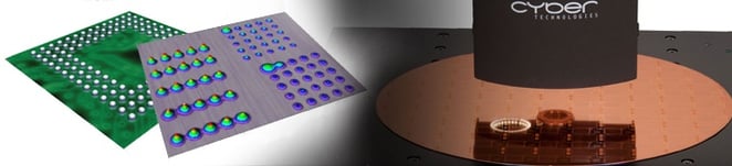
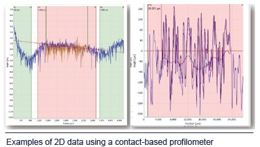
As the name suggests, this type of nano measurement solution will come in contact with the piece to be measured in order to determine its dimensions. The two main types of equipment capable of these measurements are stylus profilometers and the atomic force microscope. Both have been in use for some time and use extremely sensitive styluses to collect the measurement data required.

This type of nano-measurement is ideal if you need to measure a surface with a high aspect ratio since this can be a difficult to accomplish with optical-based solutions. These solutions have been around for a while so they are a tried and true way of measuring, and these methods are practically good at delivering 2-D data.

How do optical-based nano-measurements work?

1_3D_Image2.jpg
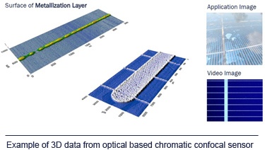
Optical-based nano-measurement technologies are quickly becoming the go-to devices for measurements at the nano level. Since these techniques do not touch the surface of the piece to be measured, there is no risk that small or delicate parts will be damaged or moved during measurement. As an added feature, optical measurements are also done more quickly than traditional contact-based measurements, and typically have an innate ability to obtain 3D measurements in addition to 2D data.

There are several methods used in optical-based nano-measurement; among them are triangulation, white light interferometry, confocal microscopes and chromatic confocal sensors. The commonality of these methods is the use of light that is emitted and then re-captured in a manner that will allow the equipment to make the extremely accurate measurements necessary to measure at the nano level.

Which type of nano-measurement is right for you?

Each of the methods listed above has benefits and drawbacks that you will need to weigh in your decision; and the decision greatly depends on what you will be measuring. As stated, contact-based measurements can make very high resolution measurements because they come in contact with the surface, but this also risks damage for delicate parts and can be much more expensive to operate.

By contrast, optical-based measurements do not risk damage to parts as only light comes in contact with the pieces, and are capable of measuring much more quickly that the contact-based methods. The drawback can be some difficulty with surfaces with high aspect ratios; such as surfaces with many features such as grooves, sharp edges, holes, steps, steep slopes or channels. So it is important to know what you will be measuring when you are choosing between the nano-measurement equipment available.

This is where the dedicated team at Q-PLUS Labs can help. Our experts have taken the time to know all the aspects of each piece of equipment best suited for each customer's application in order to recommend the best fit measurement equipment. Whether you need measurement services or help finding the right equipment for in-house measurements, our team can help. Contact us today to schedule a consultation.

New Call-to-action


Read More

Topics: dimensional measurement, 3D Scanning, nano measurement,, nanoscale,, dimensional measurement services, noncontact inspection, measurement equipment, nanometer

Q-PLUS Labs' Case Study: California State University, Fullerton Baja SAE Team's Cutting Brake 3D Scanning

Posted by Mike Knicker on Apr 6, 2016 9:03:20 AM

 banner_CSUF_Cut_Break.jpg

California State University, Fullerton’s Titan Baja SAE (Society of Automotive Engineers) team is back at it again preparing for their 2016 competition season and sought Q-PLUS Labs' measurement expertise to 3D scan a crucial component of their new vehicle, dubbed the Hyperion, the second iteration of the team’s 2015 race car, the Cronos which Q-PLUS Labs aided with 3D scanning last year. Their 2015 design of the Cronos not only competed, but beat out half the competition! This year, the team is dialing in on a design that works best for the most random and unpredictable off-road terrain which the race has been known to throw at competitors.

Introduction

Front_View.pngA little background on the rigorous Baja SAE race—it originated in 1976 at the University of South Carolina as a comprehensive engineering competition with the objective for students to function as a team and not only design, build, test, promote, and race a vehicle, but also raise financial support while balancing the demands of their course work. In order to compete as formidable opponent at the 2016 Baja SAE race, the final single-seat, all-terrain sporting vehicle is comprised of parts machined by CSUF’s Baja team.

This year, the team decided to integrate a cutting brake into the vehicle’s design. Because the race course terrain consists of extreme conditions, installing a cutting brake would help mitigate the unpredictable conditions and make the vehicle more maneuverable. It accomplishes this by working in line with the rear brake system to isolate specific wheels, giving the driver greater control of the car and facilitating with sharp terms.

Our Process

The cutting brake’s measurements are extremely vital to the vehiOurProcess.jpgcle’s ability to successfully navigate the race due to the challenging track. CSUF’s Baja team requested Q-PLUS Labs to 3D scan the cutting brake that provided the team with measurement data from which they can derive the best fit area of the car to mount the brake. Using the Steinbichler Comet 5, Q-PLUS Labs was able to give the team precise measurement data for the cutting brake, allowing a new model to be water jetted accurately while reducing the amount of time it would have taken the team to acquire the measurements manually, and helping them quickly prepare for their 2016 race in Gorman, California May 19th-22nd.


New Call-to-action


Read More

Topics: 3D scanners, 3D Scanning, 3D scanning equipment, case studies, Steinbichler, Cal State Fullerton, Baja SAE

Q-PLUS Labs 3D Scans & Renders Santa Statue

Posted by Mike Knicker on Dec 22, 2015 9:25:44 AM

ChristmasBlog2.jpg

Always looking for an interesting way to convey our holiday greeting, Q-PLUS Labs took on a unique approach to sharing holiday cheer with customers with a 3D scan of a Santa statue.

Our Process

To scan Santa, our engineers used the FARO Edge ScanArm HD which rapidly delivers point clouds with extreme resolution and high accuracy, even across different textures, including highly reflective surfaces. The scan data was then sent to Geomagic Design X, a poweful point cloud processing software for post processing, where it was quickly formed into a mesh and exported as a standard STL file.

SantaClaus_RenderPlay.jpgThe 3D file produced was a one layer, watertight mesh which was then separated into color regions. These color regions allow the mesh to be easily cut into multiple layers which were then imported into SpaceClaim to assign each individual layer its own color in context of the original Santa statue.

To render a 3D photorealistic version of the file, these colored layers into Keyshot, a program that has the ability to process and render the file in actual time. This software creates incredible visuals with 3D data and was able to produce the animations of the final rendered Santa.

PlayScreen.jpg

New Call-to-action


Read More

Topics: 3D scanners, 3D Scanning, 3D scanning equipment, case studies, Faro, holidays, keyshot, spaceclaim

Q-PLUS Labs' Case Study: California State University, Fullerton Baja SAE Team's Brake Caliper 3D Scanning

Posted by Mike Knicker on Nov 11, 2015 11:30:00 AM

 CSUF_Baja_Banner.jpg

California State University, Fullerton’s Titan Baja SAE (Society of Automotive Engineers) team sought Q-PLUS Labs’ measurement expertise to assist in jump starting the team’s 2015 season since their 2008 competition hiatus. Originating in 1976 at the University of South Carolina, the objective of this comprehensive engineering competition is for students to function as a team to not only design, build, test, promote, and race a vehicle, but also raise financial support while balancing the demands of their course work. To produce a formidable competitor at the 2015 Baja SAE race, the final single-seat, all-terrain sporting vehicle comprised of parts machined by CSUF’s Baja team from scrap, over the course of 9 months.

Introduction

2car.jpgBefore building their vehicle, CSUF's Baja team designed a virtual rendering of it in Solidworks, a 3D CAD design software. Because each piece of the car was hand machined, the team needed accurate measurements of the car’s calipers before proceeding with the build. Calipers are essential to the vehicle’s ability to stop and are one of the critical components of a car’s breaks. The challenging track consisted of rough terrain, making the measurements extremely vital to vehicle’s ability to successfully navigate the race.

Our Process

Due to its complex geometry, the calipers posed a challenge for the team to model quickly. Using Q-PLUS Labs’ 3D scanning services, the team was able to “test fit” the calipers on the solid model before it was even made. Using the FARO Edge calipers_small.jpgScanArm HD, a 3D laser scanner which rapidly collects high accuracy point cloud data, Q-PLUS Labs was able to provide the team the measurement data they needed despite the reflective surface of the calipers. The scanning information that Q-PLUS Labs provided the team reduced the amount of time it would have taken them to machine the vehicle’s parts to fit the calipers.

Defying the odds of the Baja SAE race where cars were breaking down along the grueling track, CSUF’s Titan Baja team finished the race with 11 laps. Forging ahead and looking to be in the top 20 finishing teams, they are not wasting any time preparing for 2016’s race in Gorman, California on May 19th-22nd.


New Call-to-action


Read More

Topics: 3D scanners, 3D Scanning, 3D scanning equipment, case studies, Faro, ScanArm HD, Cal State Fullerton

Q-PLUS Labs' Case Study: 3D Scanning of University of California, San Diego Statues

Posted by Mike Knicker on Sep 15, 2015 1:00:00 PM

 UCSD_Banner

The University of California, San Diego requested Q-PLUS Labs for a unique onsite 3D scanning project of the Something Pacific installation for the Stuart Collection. This installation by Nam June Paik consists of two parts, an indoor exhibit found in the lobby of the university's Media Center as well as 3 statues of tiny Buddhas staring at dead TV sets embedded throughout the landscape UCSD's Communications/Media Center building. The resulting scans will be used to reproduce the Buddha statues in detail should they be damaged or stolen.

Introduction

UCSD Statue ScanNam June Paik designed this installation which is composed of televisions paired with Buddhas watching them to depict extended contemplation. As an integral aspect of UCSD's landscape, the university sought to preserve the statues via 3D scan data in case the statues would need to be recreated in detail. For this particular application, Q-PLUS Labs' engineers used white light and laser scanning technology, specifically the Steinbichler COMET L3D and the Faro Edge ScanArm HD.

Our Process

UCSD Statue Scan

Even with high tech 3D scanning equipment, obtaining accurate and detailed scans in an outdoor and uncontrolled environment was a meticulous process. Because the statues were unmovable and anchored into the ground, the engineers established a controlled scan environment by carefully tenting each statue to block excessive lighting.

Being in an outdoor environment, the statues required thorough and careful cleaning as well as a trench dug around each statue to render more of the statues' surface area for greater scan detail. The freeform and unusual geometry of each statue also provided a challenge to obtain scan details. However, Q-PLUS Labs' engineers completed the job and the scan data produced will help to preserve this interesting exhibit for years to come.

Something Pacific       1986 Nam June Paik       Stuart Collection       UC San Diego       Photo by: Philipp Scholz Rittermann
New Call-to-action


Read More

Topics: 3D scanners, 3D Scanning, 3D scanning equipment, case studies, Faro, UC San Diego, Steinbichler, Comet L3D, ScanArm HD

More than Meets the Eye: 3 Advancements in Nano Measurement that Improved the Quality of Manufacturing

Posted by Mike Knicker on Aug 26, 2015 2:21:44 PM

More than Meets the Eye: 3 Advancements in Nano Measurement that Improved the Quality of Manufacturing

Nanotechnology has matured from science fiction into a burgeoning industry and, now, to a well-accepted component of modern manufacturing. Many people don't realize just how much nanotechnology is involved, not just for high-tech electronics and aerospace, but also for everyday applications such as adhesives, printing, and automobiles. 

As measurement capabilities have expanded from the micro to the nano scale, there has been a corresponding improvement in the quality of manufacturing across many types of industries.

3 Advancements in Nano Measurement

With the ability to provide faster, accurate results necessary to monitor quality for products requiring micro manufacturing, developments in nano measurement technologies have introduced new possibilities for manufacturers. Some of the ways that nano measurement has improved the quality of manufacturing include:

  1. Electronics - Nano measurement is commonly used for applications such as checking the size, shape, and position of solder bumps on printed circuits and determining the thickness ratios of thin films on microelectromechanical systems (MEMS).

  2. Solar cells - Analysis and quality control of solar cell manufacturing have also been improved by developments in nano measurement. Nanocrystal solar cells have a very thin coating based on silicon or a similar substrate that has a uniform coating on the surface of the cell. This coating can only be analyzed using nano measurement to confirm uniform thickness.

  3. Medical diagnostics - Advances in nano measurement are helping researchers develop medical diagnostic tools that are more sensitive and produce consistently reliable results. There are several potential applications for nano measurement in the medical field, including targeted therapy of cardiac diseases, quantitative detection devices for early diagnosis of cancer, and the development of implantable devices for in vivo diagnoses.

Because the field of nano technology is developing at an exponential level, selecting the right nano measurement device (or combination of devices) for a particular surface profilometrydimensional inspection, or reverse engineering application requires careful consideration to ensure that you receive relevant results in the necessary time frame and within your budget. The experts at Q-PLUS Labs will work closely with you to determine the best solution for you application. Contact us today to schedule a consultation.

New Call-to-action


Read More

Topics: nano measurement,, nano scanning,, nanoscale,